Storefront glazing assemblies, or “storefront” for short, are one of the most frequently used fenestration types on commercial construction projects. Ironically, it is also one of the most challenging to detail in terms of interfacing with adjacent enclosure components.
 This blog post will focus on the transition from storefront to air/water barriers (AWB), as it presents challenges due to the design of the typical storefront open backed U-channel framing profile characteristic. It will also cover how the relationship with the wall assembly impacts performance, constructability, and construction sequencing.
Background
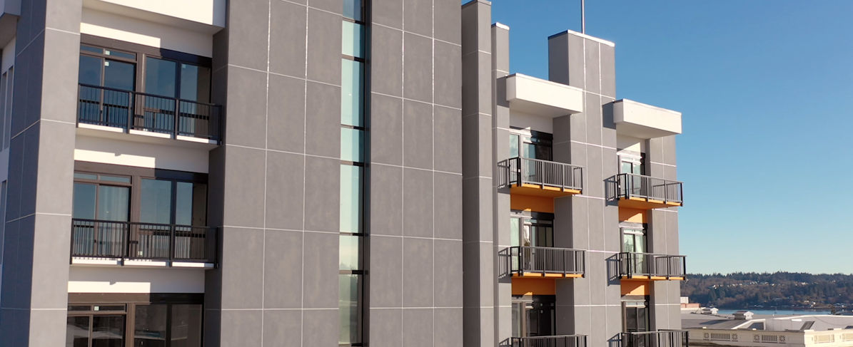
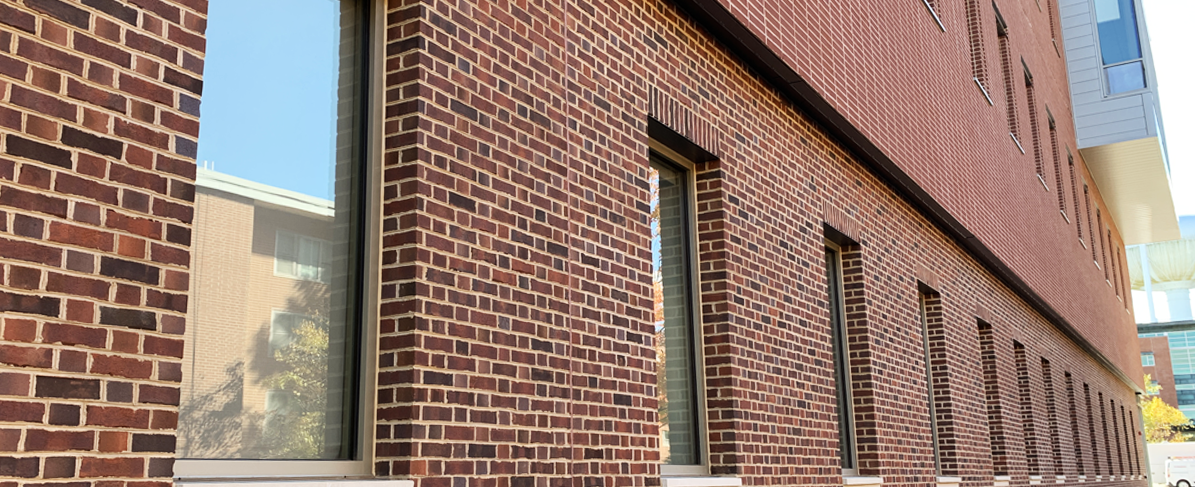
Storefront is a commonly accepted solution for conditions like retail storefronts, punched opening and horizontal ribbon conditions of office buildings, hotels, multi-family residential buildings and more. Because of its widespread use, many building enclosure failures have been associated with wall opening conditions that employ storefront. These building failures are often a product of poor or improper interfacing. Storefront glazing assemblies are typically constructed of aluminum extrusions and stick-built in the field. The main components include a head, sill and jamb framing member. Larger openings can include intermediate horizontal and vertical mullions to allow for multiple lites of glass. Further, subsills are often incorporated under the framing at the sill; head and jamb receptors are also common.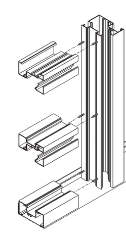
Design and Performance
The most important step when determining how to interface building enclosure materials, systems and/or assemblies with the storefront, is to first recognize the design of each system independently in terms of air, water and thermal control. With components like AWBs, it is easier to understand the control strategy; however, with fenestration or roof assemblies, for example, it may not be as intuitive. How does the product control water? How does it control air? Is air and water control provided by the same material? How do these control layers affect thermal performance? It is critical to have these answers as they will guide the rest of the product design and application processes.
For the purposes of this blog, let’s look at storefront and its relationship with drainage wall assemblies (drainage wall). This marriage is arguably the most challenging in terms of interfacing due to the inherent cavity condition of the drainage wall compared to the other wall assembly types (e.g. barrier and mass walls).
As noted, drainage walls include a cavity between the exterior cladding and back-up wall condition (drainage plane) that must be closed off at openings. Often, storefront is aligned such that it extends out from the drainage back-up wall to the cladding for this purpose. This leaves the storefront framing exposed to the open cavity at the perimeter if a separate cavity closure is not provided. The storefront framing by itself is not designed to control air or collect/drain water inboard of the exterior (primary) seal line. Without a connection between the storefront primary seal and the AWB, water can gain access to portions of the storefront framing inboard the exterior seals, which results in uncontrolled water infiltration. This uncontrolled water can collect at the top of insulated glass unit (IGU) resulting in premature IGU seal failure, leaks through storefront frame joinery into the building, or migration deep into the rough opening cavity where it is more likely to damage interior building components. Furthermore, cavity air flow can bypass the thermal break of the storefront, negatively impacting thermal performance and increasing condensation risk.
You might ask, “What about the cladding flashing at the opening; doesn’t that protect the storefront frame?” Yes and no; while flashing is critical in its role of controlling bulk water, it is simply not reliable when it comes to continuous air and water control at the storefront/AWB interface. Details often do not provide a consistent and continuous application of cladding flashing around the perimeter of the opening and blind bed seals, laps and splices associated with cladding flashing are prone to deficiencies and failures.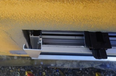
How to Address the Wall Cavity
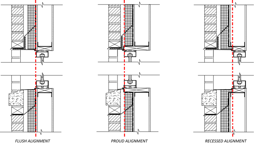
Many designers and builders have recognized the issues with storefront interfacing, but the solutions to address the cavity add complexity to the design. Alignment of the storefront within the wall will determine what opening requirements are needed to facilitate the connection of the storefront primary seal and AWB. Note that in the images below, the red dashed line represents the drainage plane of the storefront framing which is consistent, yet often different from the drainage plane of the wall.
- A flush alignment aligns the storefront frame with the back-up wall which makes the tie-in from the primary seal to the AVB a bit easier. Cladding returns or metal flashing is typically used to close off the wall cavity.
- A recessed alignment is much like a flush alignment in terms of solutions for closing off cavity conditions.
- For a proud alignment, a metal collar flashing or wood blocking (shown in examples below) can be used as means to “extend the line of air and water control out” to receive the exterior seal of the storefront. The metal collar flashing would be detailed similar to wood blocking, except it consists of continuous perimeter brake metal angle that is sealed or wrapped with AWB flashing membrane. Some storefront manufacturers promote an extruded silicone sheet for this transition to extend and seal the storefront framing in lieu of a metal collar flashing or blocking.
In many cases, cladding/metal flashings are utilized to close off the wall cavity back to the storefront frame, but this presents the challenge of where to attach it at the opening. It is common practice in the industry today to extend the perimeter flashing into the opening, however as noted above this is problematic in terms of performance for many reasons, but especially at terminations and splice joints. Extending metal flashing into the perimeter joint of the storefront opening also creates a very impactful construction sequencing challenge. To affix the flashing mechanically within the rough opening, the storefront must be left out. And because the cladding flashing typically needs to be installed in sequence with the cladding, this often delays the installation of the storefront to occur after the cladding installation is complete. This then delays the start/completion of interior finishes to until the building can be “dried in”.
Best practice is to incorporate detailing which accommodates storefront assembly installation prior to the cladding. This also allows the storefront glazing assembly to be field tested when all adjacent air and water control layers are exposed, making it easier to diagnose and correct issues. Additionally, the building is dried in quicker, mitigating the need for temporary tarping. This methodology can help to compress construction schedules as building interiors can be installed simultaneous to exterior cladding, that is of course as long as the roof is installed or at least installed temporarily in a water-tight fashion.
With any of the alignments noted above, there will be challenges with the exterior seal, as it typically must perform a dual role, the primary seal and the aesthetic seal. To add more difficulty, there is often a limited return surface on the storefront framing in which to receive the sealant joint at the perimeter conditions. Further, the top of the jamb members and intermediate vertical mullions are hollow, providing minimal surfaces for sealant adhesion.
If tolerances of the back-up wall, storefront and cladding/flashing can be tightly controlled, the exterior seal can be simultaneously sealed to the storefront, AWB and flashing/cladding. This is assuming the perimeter flashing are bent and affixed to the face of the back-up wall (vs. deeper into the opening condition) or if the cladding were to return tight to the rough opening, respectively. Contractors typically shy away from this approach, as it is difficult to install perfectly. As noted earlier this approach also delays installation of the primary sealant joint and often impacts the wall assembly thermal continuity such as when the cladding returns close off the wall cavity, interrupting the wall assembly continuous insulation.
An alternate but similar approach would be to “strip in” the perimeter metal flashing with AWB flashing membrane to integrate the metal flashing with the AWB. This can be an effective option but requires both the metal flashing and the AWB flashing to be installed before the storefront; which presents a similar sequencing challenge as noted above. This is due to the perimeter metal flashing being part of the cladding assembly.
Conceptual Detail Solutions
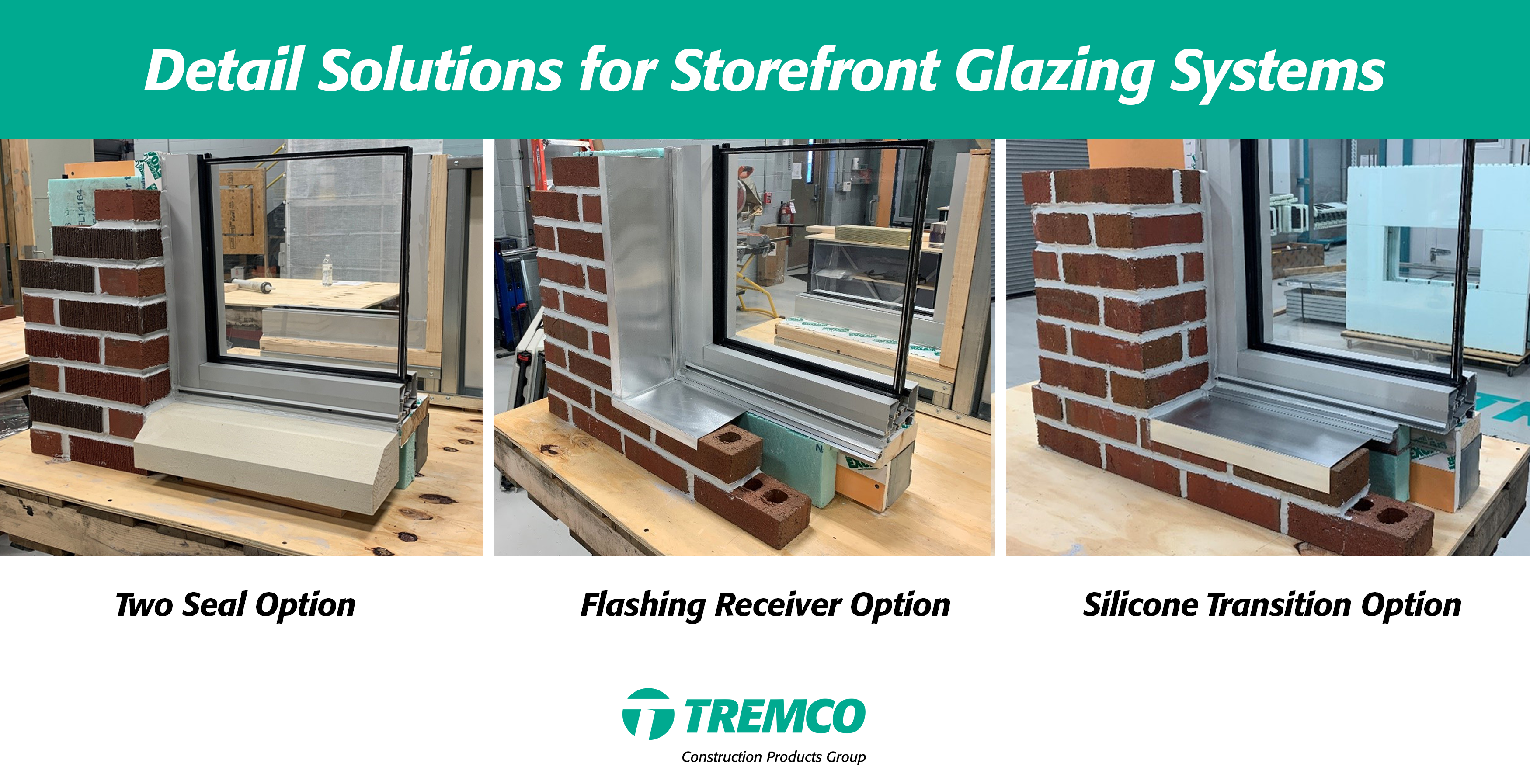
Let’s consider the following detailing options that address performance and sequencing challenges noted above. Three mockups using the Kawneer Trifab® 451UT Storefront Framing System were constructed at the Tremco CPG Building Science Laboratory in Cleveland, Ohio to demonstrate these detailing options.
- Two Seal Option: Two seals are employed at the exterior side of the system; the inner seal of the two seals acting as the primary seal and the outer exposed seal performs as the aesthetic bulk water seal. This requires modifications to the storefront due to the open jamb/intermediate vertical mullions that typically terminate at the head condition, as the open mullion does not provide a substrate for the perimeter sealant joint. Therefore, the mullions must be capped/sealed to accommodate the additional sealant joint; this is best practice for any storefront installation; however, always check with manufacturer before modifying system.
- Flashing Receiver Option: Incorporate a flashing receiver, similar to York AirSill® Type A, or clip angle at opening that can receive the metal flashing and allow direct connection of the exterior (primary) seal and AWB.
- Silicone Transition Option: Integrate a silicone sheet, similar to Tremco Proglaze® ETA, as the primary seal. A flashing receiver, like York AirSill® Type B, can also be incorporated to receive metal flashing in conjunction with the thermal Z-girt to allow for continuous thermal control up to storefront framing; shown here at the sill only.
The conceptual details provided above are successful at addressing performance concerns as well as construction sequencing challenges. Each allow for direct connection of the primary seal and AWB, and the installation of the storefront can be completed prior to cladding and perimeter flashing. Also note that all details include a continuous interior perimeter seal that also engages the AWB, sometimes referred to as the interior “air seal”; this interior seal should always be included and functions as a redundant air seal. Every project has its unique challenges and can be solved a number of different ways; the details provided are a guide to addressing the most prominent issues related to storefront construction.
Special thank you to Matt Freeborn, B&G Glass, for providing the storefront samples and to Marcy Tyler and Phil Effler, Tremco Commercial Sealants and Waterproofing, for helping build these mock-ups.