The coping at the parapet-to-wall interface condition is one of the most difficult transitions to detail for design professionals and contractors. Due to complex geometries, direct exposure to the elements, and sequencing of construction trades, there are numerous areas for potential failure at this condition that can lead to air and moisture leakage issues within buildings. Learn more about parapet walls here.
During construction, these leaks can be disruptive, leading to change orders, construction delays, water-related damage, and construction claims. After the building is occupied, tracking down these leaks can be a source of frustration for the building owner, falling back on the architect and contractor for a solution. Let’s review these challenges to better understand how the architect can address these conditions during the design, pre-construction, and construction phases to mitigate the risk of water infiltration.
Challenges of Coping Terminations at Parapet-to-Wall Conditions
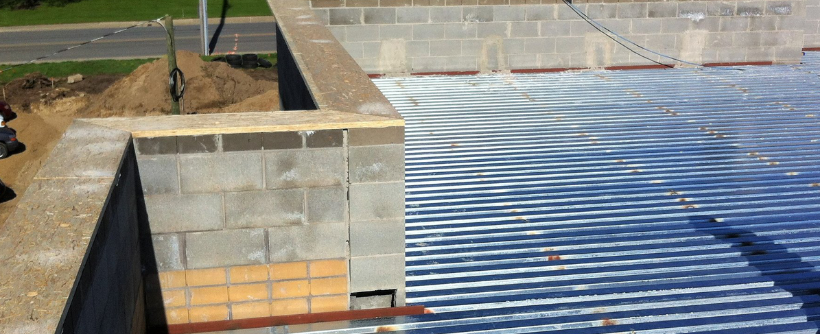
Complex Geometries - Architects often include wall sections and enlarged details showing the roofing membrane extending up and over the parapet wall beneath a sheet metal coping. Similarly, they may detail the roof-to-wall connections at stepped roof conditions using roof counter-flashings and through-wall flashing assemblies. The interface between these two conditions presents complex geometries necessitating careful detailing of the roofing membrane, weather-resistive air barrier (WRAB), through-wall flashings, counter-flashings, and copings to mitigate the risk of water and air leakage.
Proper detailing is needed to maintain continuity of the air and moisture control layers at parapet-to-wall conditions. In my experience, saddle flashing details showing the integration of these materials at the coping termination-to-wall condition are not often drawn or specified in design documents. Not having saddle flashing details and specifications requirements in the contract documents can lead to varying field installations and discontinuities in the control layers, which in turn can result in water infiltration problems.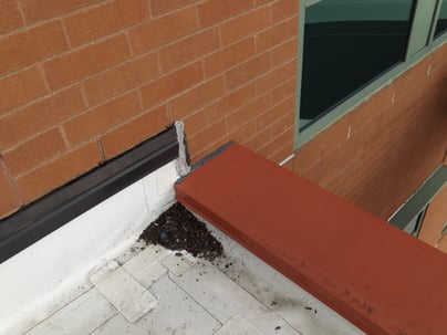
Direct Exposure to the Elements -My investigative findings have shown inconsistencies in the manner in which the roofing membrane terminations are installed at the end of parapet-to-wall conditions. In some instances, the roofing membrane is installed with an upturned leg that is secured to the wall framing and sealed to the WRAB. In others, the roof membrane is installed with the cut edge terminating horizontally at the wall with no integration with the WRAB. Additionally, when the roofing membrane is installed with an upturned leg at the wall, the contractor seldom incorporates continuous side flanges to wrap the top of the parapet wall and provide full continuity of the roofing membrane and WRAB.
Similarly, the method in which the ends of sheet metal copings interface with the wall cladding vary widely. Some of the more common ways I have seen the ends of copings detailed include the following: 1) the coping terminates horizontally at or near the surface of the wall cladding; 2) the coping extends into the wall cladding (for example, masonry or EIFS) without an upturned leg and integral side flanges; and 3) the coping terminates within the wall cavity or cladding with an upturned leg and no side flanges.
In these examples, a bead of sealant is often detailed at the interface between the coping and the surface of the wall cladding. However, the sealant can fail due to improper joint/sealant bead geometry, under-accommodated thermal movement, or deterioration of the sealant, and without effective flashings below the coping, water infiltration can occur.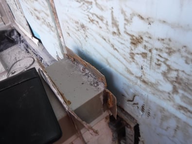
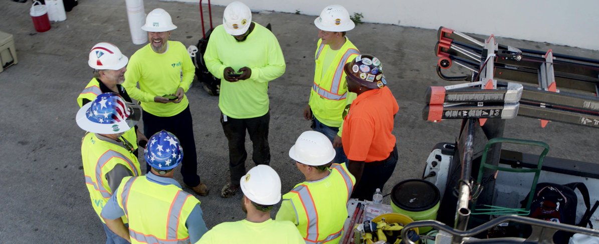
Trade Sequencing -Since saddle flashing conditions typically involve multiple building materials, including one or more types of wall cladding, roofing, through-wall flashings, counter-flashings, and WRAB, the construction sequencing and constructability needs to be carefully reviewed by the design professional, construction manager, building enclosure consultant, manufacturer, and construction trades. The process and responsibilities should be reviewed during the design phase, pre-construction, and construction. I recommend employing mock-up walls that incorporate the project specific materials associated with the saddle flashing condition to confirm and adjust the detail so that it is constructible and sequenced properly. Performance testing should be considered for the mock-ups and installed saddle flashing to confirm that it performs as intended
Saddle Flashing Design Resources
Industry recognized examples of saddle flashing are generally limited to standard details provided by some EIFS and stucco manufacturers, and a singular detail included in the current Sheet Metal and Air Conditioning Contractors' National Association (SMACNA) Architectural Sheet Metal Manual. These details can be a helpful starting point for design professionals but will need further development based on each project’s specific building design and selection of materials.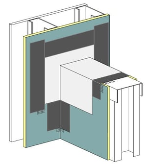
In EIFS and stucco applications, the details (see image right)typically include a sheet metal saddle which straddles the parapet with two sheet metal side flanges at the parapet-to-wall interface condition, all of which are detailed in a shingled manner to shed water to the exterior. The saddle flashing detail within the SMACNA manual illustrates a sheet metal saddle that straddles the parapet wall and extends through the brick veneer with an integral upturned leg and side flanges within the drainage cavity. Since details in the SMACNA manual are intended to provide guidance for the design and installation of custom-fabricated sheet metal, they do not show the connections of the air and moisture control layers. Industry organization standard details are still needed to illustrate the integration of sheet metal saddle flashing with the weather-resistive air barrier, flashings, cladding, and roofing to provide resistance to air and water leakage.
How Architects Can Help
The following are some actionable steps to reduce the risk of air and water leakage at saddle flashing conditions:
- Where feasible, simplify the design of parapet-to-wall conditions by minimizing the number of wall cladding materials and fenestration systems that occur at the parapet termination against the adjacent high rising wall condition.
- Develop multi-step, three-dimensional diagrams to convey the design intent in a clear and concise manner to the contractors. Three or more details are strongly recommended to convey the integration of building materials.
- Involve the manufacturers in the design development of the saddle flashing.
- Language within applicable technical specifications should require the following for the saddle flashing: project specific shop drawing details that show the integration of the saddle flashing and the adjacent materials, product materials and characteristics, installation requirements, mock-ups, and performance testing.
- Consider engaging a building enclosure consultant to provide design assistance or peer review services associated with detailing and specifying the saddle flashing condition as well as other complex details and conditions.
- Require project-specific saddle flashing mock-ups for review, critique, and further development by the design and construction team.
- Review each unique saddle flashing condition with the construction trades to confirm constructability of the detail and proper sequencing.
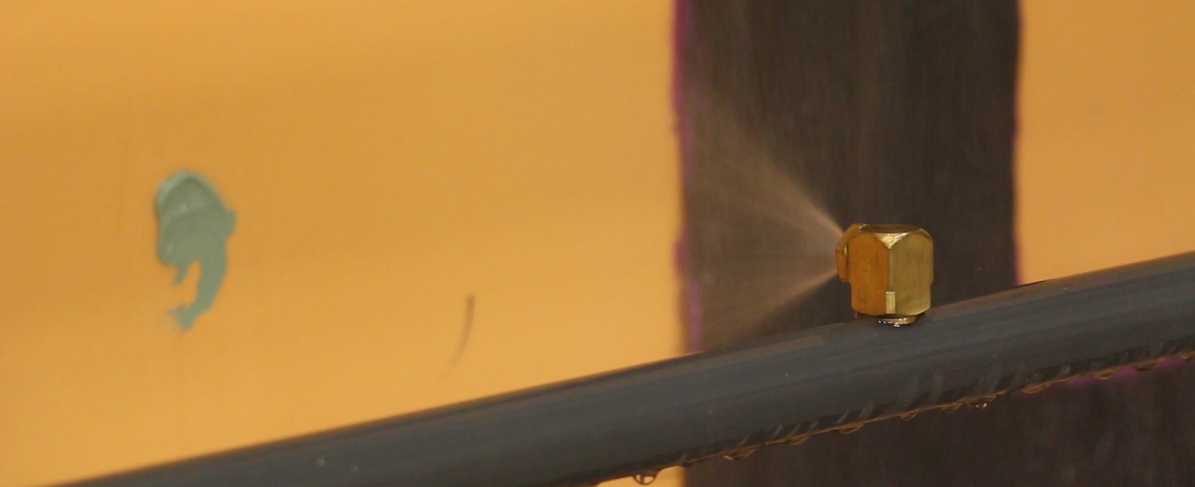
- Incorporate performance testing of the mock-up and installed saddle flashings at representative areas to evaluate the watertight integrity of the condition.
- Require pre-construction meetings to review requirements of the saddle flashing conditions and integration with other materials.
Due to the limited amount of industry recognized saddle flashing details, I developed a set of multi-step isometric details showing the integration of the WRAB, roofing membrane, through wall flashing, counterflashing, and sheet metal flashing for inclusion in one or more industry recognized standard detail manuals.
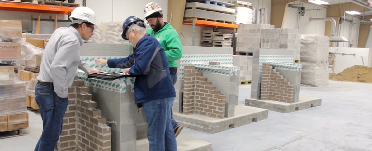
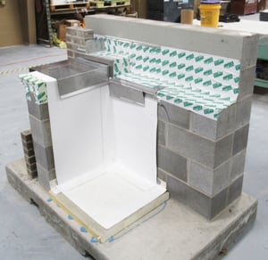
Between 2019 and 2020, Wiss Janney Elstner Associates, Inc. (WJE) collaborated with the Bricklayers and Allied Craftworkers of Local 5 Ohio, International Masonry Institute (IMI), Tremco Commercial Sealants and Waterproofing, and Warren Roofing to construct three mockups to show a typical saddle flashing detail at various stages in the installation process. IMI and WJE plan to utilize the mockups as an educational tool for design professionals, building enclosure consultants, manufacturers, contractors, and industry organizations. WJE has agreed to assist the IMI by developing a set of saddle flashing details to be incorporated into the IMI online detail series.
Watch the project in action here: